
Hewlett-Packard HP-97S
| Datasheet legend
Ab/c:
Fractions calculation
AC: Alternating current BaseN: Number base calculations Card: Magnetic card storage Cmem: Continuous memory Cond: Conditional execution Const: Scientific constants Cplx: Complex number arithmetic DC: Direct current Eqlib: Equation library Exp: Exponential/log functions Fin: Financial functions Grph: Graphing capability Hyp: Hyperbolic functions Ind: Indirect addressing Intg: Numerical integration Jump: Unconditional jump (GOTO) Lbl: Program labels LCD: Liquid Crystal Display LED: Light-Emitting Diode Li-ion: Li-ion rechargeable battery Lreg: Linear regression (2-var. stats) mA: Milliamperes of current Mtrx: Matrix support NiCd: Nickel-Cadmium recharg. batt. NiMH: Nickel-metal-hydrite rech. batt. Prnt: Printer RTC: Real-time clock Sdev: Standard deviation (1-var. stats) Solv: Equation solver Subr: Subroutine call capability Symb: Symbolic computing Tape: Magnetic tape storage Trig: Trigonometric functions Units: Unit conversions VAC: Volts AC VDC: Volts DC |
| ||||||||||||||||||||||||||||||||||||||||||||||||||||||||
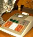
 The HP-97S is an ingeniously modified version of the popular HP-97 programmable calculator. The modifications make it possible for the calculator to perform input/output functions.
In the pre-PC era, such calculators provided a low-cost means to control laboratory experiments, test equipment, and other electronics.
The capabilities of programmable calculators are best demonstrated through programming examples, such as my favorite, the Gamma function. But how do you demonstrate the capabilities of an "I/O calculator"? Why, by building a suitable device of course that interfaces to, and is controlled by, the calculator.
As part of my electronics hobby, I just recently built a small, low-power clock. Using CMOS circuits, the clock consumes only a few µA of power and runs off a 3V lithium battery. Such a circuit seemed like an ideal project for my newly acquired HP-97S. So I decided to build a clock that provides the current time in the form of HH.MMSS (the time format used by the DMS conversion function of the HP-97S) and can also be set through a combination of flags.
Building this circuit was not without problems; some were foreseeable in advance, whereas others weren't.
 First, the issue of current drain. If the outputs of the clock circuit are connected to the inputs of the BCD interface of the HP-97S, there will be a considerable current drain on any output that is at a logic high level. Fortunately, since the inputs of the HP-97S have internal pull-up resistors, the external circuit only needs to provide sink current; in other words, it is possible to protect the device against current drain by simply inserting a set of diodes.
Second, the device must be protected against transients when the HP-97S is powered up or down. One way to do this is to set the clock using a combination of flags that would not normally occur, and filtering transient noise that may occur during power up/down events.
Third, I found that when the HP-97S reads data using the method recommended in the manual, sometimes it "swallows" the first digit. I don't know if this is just a fluke on my machine or a behavior common to all HP-97S calculators, but I had to protect against it. The simplest solution was to just insert a leading 0 before any data; since I am not using all 10 BCD digit positions, I was able to afford this method.
So how does my clock work? As shown on the block diagram on the right, it consists of a simple circuit of counters; starting with a crystal frequency of 32768 Hz, seconds, minutes, and hours are obtained through several counter phases. Counter outputs are fed directly to the HP-97S BCD interface in the following format:
Flags 1 and 2 are used to set the minutes and hours, respectively. However, they are first gated with a combination of flag 3 and the inverse of flag 0. This combination does not occur during normal operation; during power on/power off events, the device is protected against transients using a single capacitor as filter, so that the clock is not set inadvertently.
Here is a program that can be used to both continuously display the current time (A) or set the minutes (B) or hours (C).
001    21 11     *LBL A
002    16 51      PSE
003    16 22 03   CF3
004    51         R/S
005    21 16 14  *LBL d
006    16 21 01   SF1
007    16 21 02   SF2
008    16 21 00   SF0
009    16 22 03   CF3
010    24         RTN
011    21 16 15  *LBL e
012    16 21 03   SF3
013    16 22 00   CF0
014    16 22 01   CF1
015    16 22 02   CF2
016    24         RTN
017    21 12     *LBL B
018    23 16 14   GSB d
019    16 22 01   CF1
020    16 21 01   SF1
021    23 16 15   GSB e
022    16 22 03   CF3
023    51         R/S
024    21 13     *LBL C
025    23 16 14   GSB d
026    16 22 02   CF2
027    16 21 02   SF2
028    23 16 15   GSB e
029    16 22 03   CF3
030    51         R/S
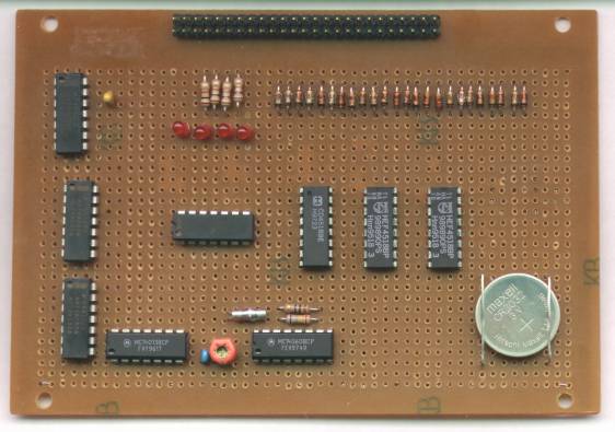 A picture of the completed breadboard version of this circuit is shown on the right. The extra four resistors and red LEDs were used for diagnostic purposes only, and can be omitted; their presence is not required for the clock's operation (they're used to indicate the state of the calculator's flags.)
A detailed block diagram of the clock circuit is reproduced below. The clock is constructed using the following off-the-shelf integrated circuits:
| Quantity | Type | Description |
| 1 | 4013 | D-type flip-flop |
| 1 | 4060 | 14-bit counter |
| 1 | 4081 | Quad 2-input AND gate |
| 3 | 4518 | Dual BCD counter |
| 2 | 74HC00 | Quad 2-input NAND gate |
| 1 | 74HC04 | Hex inverter |
 As for the diodes used to protect against current drain, you can use any silicon signal diodes (e.g., 1N914). The circuit runs off a CR2032 lithium battery.